Modeler User Interface Overview
Modeler’s screen is divided into several areas. By default, the workspace of the screen consists of four viewports. Modeler displays four simultaneous points of view (Top, Back, Right, and a forced-perspective view), each looking at the same portion of the workspace from a different angle. These are not unlike Layout’s viewports. Changes made in one view are immediately updated in the others.
01 and 02. ToolBar, 03. Modeler Tabs, 04. Current Object, 05. Layer Bank Selection 06. Layers,07. Layout Access, 08. Workspace, 09. Info Display, 10. Grid Display, 11. Selection Info, 12. Progress Bar, 13. Tool Tip, 14. Edit Mode, 15. Action Centers, 16. Symmetry, 17. SubD Type, 18. Numeric Window, 19. Change Surface, 20. Drop Tool, 21. Drop/Restore Selection, 22. Undo / Redo, 23. Vertex Maps
Each area of Modeler’s Interface is fully customizable in the Configure Menus Panel (Alt + F10).
01 and 02. ToolBar
The toolbar sits at the side of the screen. The buttons presented will vary depending on which menu tab you select along the top. The Top Tool Bar buttons in section 1 will appear no matter which Tab is selected. You can completely hide (or unhide) the toolbar by pressing Alt +F2 (or choosing Edit > Display Options > Interface > Hide Toolbar On/Off).
Hiding Panels
Since your screen can often get cluttered with open panels, you can quickly hide/show these floating windows by pressing Alt +F1.
03. Modeler Tabs
The Tabs located at the top of the interface will determine which tools appear in the Toolbar. Each Toolbar is divided into menu groups. Generally, menu group names that are verbs contain commands based on the type of action they perform. Menu group names that are nouns contain commands based on the type of object they affect.

- Create - Primitives, Points, Polygons, Curves and more.
- Modify - Move, Rotate, Transform, and more.
- Multiply - Expand on existing geometry.
- Detail - Tools to detail your object.
- Construct - Reduce and combine points and polygons and much more.
- Map - All the tools you need to create and manage Vertex Maps.
- UV - The tools specific to UV vertex maps.
- Setup - Skelegons and other tools that can be used inside Layout.
- Selection - Tools related to selecting points, edges and polygons.
- Layers - Controlling an object’s layers and tools for managing layers.
- View - Display options and selection tools can be found here.
- I/O - Tools related to imported and exporting for Modeler.
- Utilities - 3rd-party tools or your own scripts.
04. Current Object
Like files in your word processor, multiple object files can be loaded simultaneously. The Current Object pop-up button to the left of the layer buttons switches from object to object. Object names listed with an asterisk (*) have been changed and may need to be saved. Attempting to close the application triggers a request to save all changed objects. Ghosted objects are ones that have been loaded into Layout, but not into Modeler. Choosing a ghosted object from the pop-up menu will load it.
Use the Current Object pop-up menu to select which object you are editing.
05. Layer Bank Selection
You can use the layer buttons in the top-right corner of the main interface to work with layers in banks of ten. LightWave gives you unlimited banks of ten which can be accessed here.
06. Layers
Every object can be a “MultiMesh”, that is, consist of an unlimited number of layers, similar to layers in many paint programs. The MultiMesh lets you work independently on specific parts of an object. During Modeling operations, you can set layers independently to be in the foreground or background, so you can work on a combination of layers as if they were in the same layer. Background layers can be used as a reference, but are often required when using certain Modeling tools.
07. Layout Access
This drop down menu gives you the following options:
- Switch to Layout - switches to your Layout window if it is open or opens up Layout if you do not already have it open.
- Synchronize Layout - Changes to objects in Modeler are reflected automatically in Layout when you select the Layout interface. You can force this synchronization by choosing this option.
- Send Object to Layout - sends the current object to Layout. Actually, it sends a pointer to the current object’s file. As such, the object must be saved to your hard drive first.
These options assume that you have the Hub running.
08. Workspace
By default, the workspace of the screen consists of four viewports. Modeler displays four simultaneous points of view (Top, Back, Right, and a forced-perspective view), each looking at the same portion of the workspace from a different angle. These are not unlike Layout’s viewports. Changes made in one view are immediately updated in the others.
The crosshair at the center of the four viewports can be grabbed and moved where you want. If you have fewer than the normal four viewports, the borders between viewports can be used for resizing.
Viewport Titlebar
You can change the View Type and Rendering Style of a viewport without going to the Display Options Panel by using the pop-up menus on the left side of each viewport titlebar.

The buttons on the right side affect panning, rotating, zooming, and minimizing/maximizing your view.

See Working with Modeler Viewports for more info.
09. Info Display
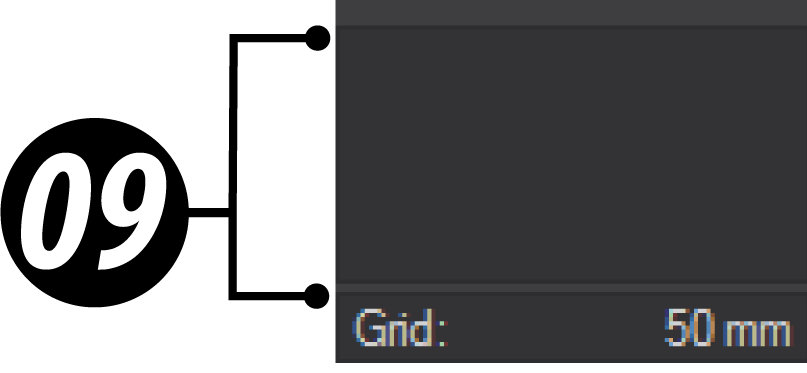
Just above the grid display is an information display. Most of the time this gives you feedback on the position of your mouse. However, depending on what you are doing, it can also display a variety of other information.
10. Grid Display
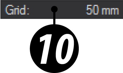
In the bottom-left corner of the screen, you can see the grid size information display. As in Layout, this tells you how big each square is in the Modeler workspace.
11. Selection Info
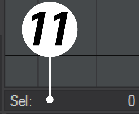
Above the Edit Mode is the selection info display, which tells you how many points, edges or polygons you have selected.
12. Progress Bar
Displays tool processing.
13. Tool Tips
Displays helpful information for current tool.
14. Edit Mode
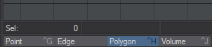
To the right of the grid display are four mode buttons. These are mutually exclusive buttons, so only one can be active at any one time. These determine when you are editing Points, Edges or Polygons using the Spacebar cycle. You can also select Volume mode from this section.
15. Action Centers
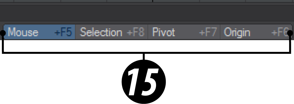
These tell you how any modification is going to be made to geometry - based on the position of your mouse pointer, based on the center of the selection, the pivot or the origin.
16. Symmetry
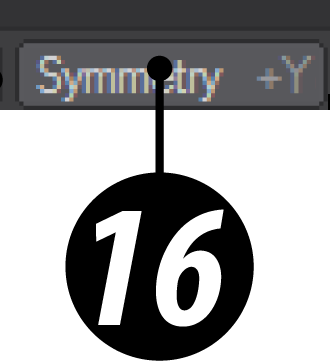
The Symmetry mode (Symmetry button, located along bottom edge) not only works on selection but also on editing. Operations on the positive side of the X axis also inversely affect the negative side of the X axis. When this mode is active, your object is theoretically split in half at X=0.
17. SubD Type
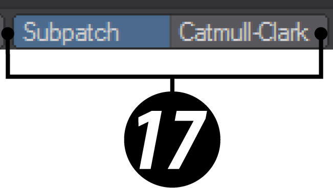
Allows you to switch between two SubDivision modes, Subpatch and Catmull-Clark.
18. Numeric Window

You can enter numeric values for every tool in Modeler. Access it at the bottom of the interface.
19. Set Surface

Activates the Change Surface Panel to set the surface name and basic attributes for the selected polygons. See Surface Editor for more information.
20. Drop Tool

Finalizes your adjustments to geometry.
21. Drop/Restore Selection
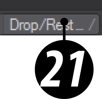
Deselects all selected geometry.
22. Undo / Redo
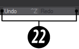
Button equivalents for the Ctrl -Z / Z operations.
23. Vertex Maps
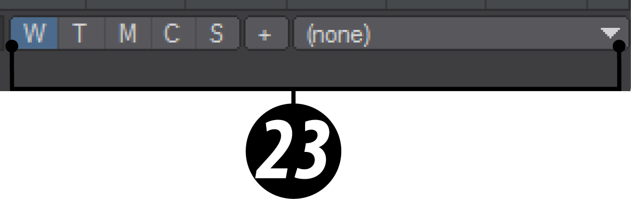
VMaps can be created using the buttons in the lower-right corner of Modeler. In a way, you can think of Vmaps as “surfaces” for points. It's a way of tagging some information onto points that allow much more control of various Lightwave functions on a point level. The + button will create a new Vmap in the VMap type currently selected from this list:
W - Weight, T - UV Texture, M - Morph, C - Color, S - Selection Set.